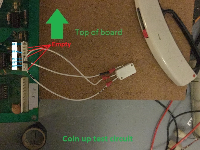
- Get a 9 pin Molex KK type (".1") header plug.
- Take a 10000 Ohm resistor and plug it into the headers between pin #1 and #4 on the header sockets.
- Take a normal joystick microswitch, connect the "NO" terminal to pin #6 on the main logic board headers
- connect COMMON on the microswitch to pin #7 on the logic board headers
- connect the "NC" terminal to ping #8 on the main logic board headers.
- Make sure pini #2,#3, #5 and #9 are blank/empty
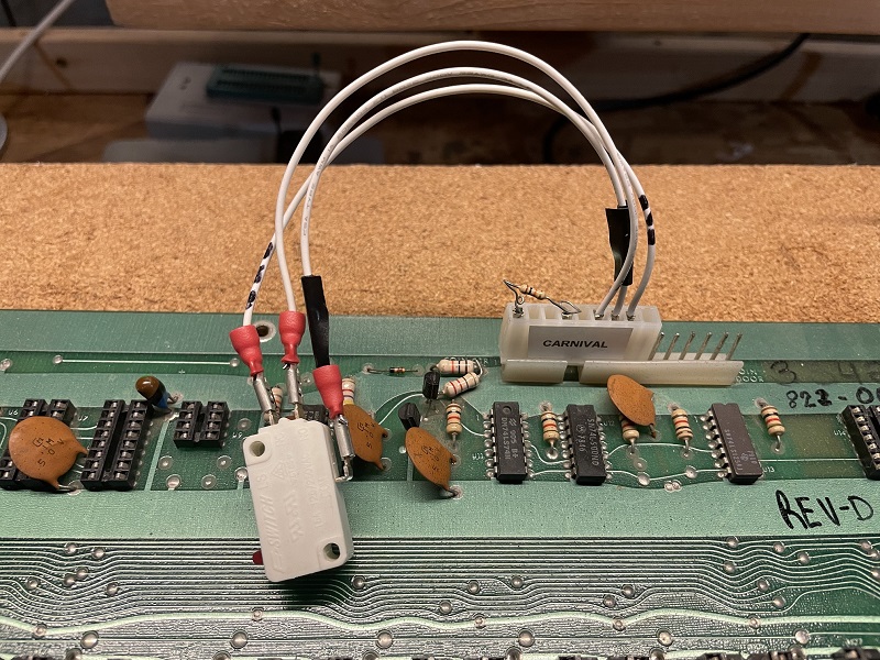
If you are using a VIC 1 board (like Head On) setup the connector as shown in this picture
Information on Sounds
The sounds in carnival are triggered by writting certain bits to an IO address. The data is read directly off the data bus by 2 74LS374 flip flops at U63 and u64. For the sounds in the table below you can test the sound by manually grounding the respective pin. Here is the information| PCB header pin | Sound | Chip U63 or U64 | Pin on chip | I/O address | Bit position (0-7) |
| 29 | Bonus #2 | U64 | 12 | 7 | |
| 30 | Bonus #1 | U64 | 9 | 6 | |
| 31 | Pipe | U64 | 15 | 5 | |
| 32 | Duck #3 | U64 | 6 | 4 | |
| 33 | Duck #1 | U64 | 5 | 2 | |
| 34 | Duck #2 | U64 | 16 | 3 | |
| 35 | Clang | U64 | 19 | 1 | |
| 36 | Rifle | U64 | 2 | 0 | |
| 43 | Ranking | U63 | 15 | 5 | |
| 45 | Bear | U63 | 5 | 2 |
Carnival, Main PCB to Music Board
| PCB header pin | Sound | Chip U63 or U64 | Pin on chip | I/O address | Bit position (0-7) |
| 44 | ??? to Music Board | U63 | 6 | 4 | |
| 46 | ??? to Music Board | U63 | 16 | 3 |
Main PCB header pins 49-52 are to provide power to the sub boards.
| PCB header pin | Voltage |
| 49 | +12 |
| 50 | -12 |
| 51 | Ground |
| 52 | +5 |
0xc000 - 0xc37F - tiles
0x93:0 -> 0x9c: 9
Tiles (bottom left = 0x00, moving up and over to the right)
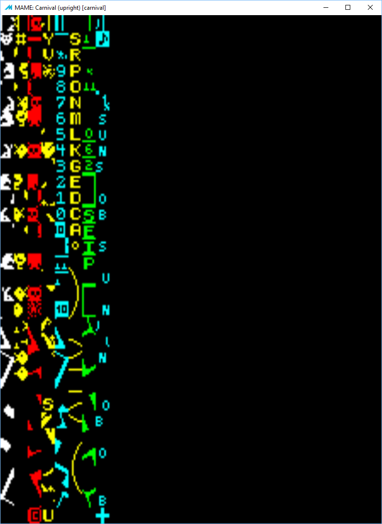
Note: pulsar has the entire alphabet at it's ASCII values (0x41 = A - Z), and 0-9 at (0x30 - 0x39)
Important Note: The carnival hardware has ROM from 0x0000 - 0x3FFF HOWEVER it is mirrored into 0x4000 - 0x7FFF and this mirror MUST exist! The code calls routines in this upper address space (0x4000 etc) so if it's not mirrored things don't work!
RAM is also from 0x8000 - 0x8FFF but the hardware maps this into each areas (0x9000 - 0x9FFF, 0xa000 - 0xaFFF... 0xf000 - 0xffff) but the range at least in carnival uses 0xe000 - 0xefff